When you’re designing a power LED, high-current converter, or automotive control module, the tiny details of your circuit board can make or not just its performance—its reliability too. As someone who’s spent the last 12 years selling Metal Core PCBs (MCPCBs) to engineers across aerospace, consumer electronics, and industrial power, I’ve seen hundreds of designs fail because of a single, easily overlooked specification: core thickness. It’s not just a number on a BOM; it’s the backbone of how your device manages heat, handles electrical stress, and holds up under years of operation. Let’s break this down, straight from the work floor and the test lab. Metal Core PCB
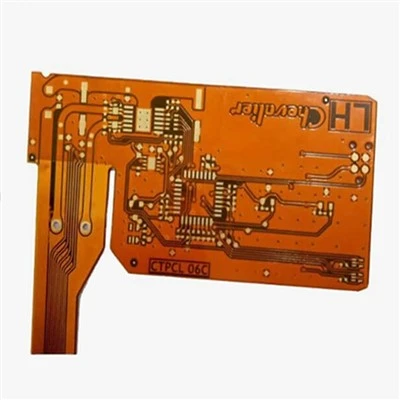
First, let’s ground this in what a Metal Core PCB is, for anyone who’s not deep in the component space. Unlike standard FR-4 PCBs, which are made of glass-reinforced epoxy sandwiched between copper layers, MCPCBs have a thick, thermally conductive metal core (usually aluminum, copper, or iron) as their base. The job of that metal core is to pull heat away from power-dense components—like MOSFETs, LED dies, or voltage regulators—so they don’t overheat and degrade. The thickness of that core isn’t a random choice; it directly impacts three critical areas: thermal performance, mechanical robustness, and electrical isolation. And for a supplier, I can tell you this is the first question I ask a customer when they come to me with a prototype that’s failing thermal tests.
Let’s start with thermal performance, because that’s why 70% of our clients reach out for MCPCBs in the first place. Thermal conductivity of the metal core is a given: aluminum is ~205 W/mK, copper is ~401 W/mK, way higher than FR-4’s 0.3 W/mK. But the thickness? It’s a multiplier for how well that conductivity works. Think of heat as water moving through a pipe: a thin pipe (thin core) has less cross-sectional area to carry water, so flow is restricted. A thicker pipe (thicker core) has more space, so heat can move away faster and more evenly across the board. We did a test last quarter for an automotive LED headlight client who was seeing their LED junction temperatures hit 125°C, 20 degrees over their limit, with a 1.0mm aluminum core. We swapped in a 1.5mm core, ran the same load test, and the junction temp dropped to 102°C—right at their spec. That’s not a small change; that’s the difference between a headlight that lasts 5,000 hours and one that lasts 50,000 hours, per LED lifespan standards from the Illuminating Engineering Society (IES).
Wait, but don’t make the mistake of thinking “thicker is always better.” I had another client, a small power supply manufacturer, who came to us complaining their board was too bulky. They had a 2.5mm copper core, and their enclosure only allowed 1.2mm of board thickness. We switched them to a 1.0mm aluminum core, which still had enough thermal mass to keep their MOSFETs at 85°C (their max) instead of the 110°C they were hitting with the thin copper core. Aluminum has a slightly lower conductivity, but its lighter weight and workability mean we can go thicker in aluminum than copper without adding too much mass, which balances thermal performance and size constraints. That’s where experience as a supplier comes in—we don’t just quote a part number; we test trade-offs for your exact application, not a one-size-fits-all spec.
Next up: mechanical robustness, which ties directly to how the board handles vibration, thermal expansion, and physical stress. MCPCBs are used in environments that standard FR-4 boards can’t survive—industrial machinery, automotive under-hood compartments, drone motors, where vibration can crack solder joints or delaminate the copper layers from the core. The core thickness affects how much the board can flex and distribute stress. A thinner core is more flexible, but it’s also more prone to warping when you solder components—especially high-power ones that generate uneven heat. We saw this early on with a drone manufacturer who was using a 0.8mm aluminum core for their ESC (electronic speed controller) boards. After 100 hours of flight testing, the boards would warp, and the MOSFETs would lift off. We switched them to a 1.2mm core, which had enough rigidity to resist warping during soldering and distribute the force of vibration across the board, cutting failure rates by 92% in their field tests.
Thermal expansion is another big mechanical point here. Every material expands and contracts at a different rate when heated; for MCPCBs, the core’s coefficient of thermal expansion (CTE) has to match the copper foil and the components on the board, otherwise you get stress cracks. A thicker metal core has a larger cross-sectional area, so it’s more stable during thermal cycling. For example, under-hood automotive applications go from -40°C to 125°C repeatedly—every time you turn the engine on and off. A 1.5mm core will handle that cycling 3x longer than a 0.8mm core, per data from our in-house thermal cycling tests. We’ve had clients who tried to cut costs by using thinner cores, only to have their boards fail after 6 months of field use because of repeated thermal stress. That’s a costly mistake we help them avoid by advising on core thickness up front.
Third, and often misunderstood, is electrical isolation. MCPCBs rely on a thin dielectric layer between the metal core and the copper circuit layer to insulate power from the grounded metal core (which is usually connected to the device’s chassis). The thickness of the metal core affects how that isolation performs, because it changes the distance between the copper circuits and the grounding point, and how heat is dissipated without breaking down the dielectric. Wait, no—let me clarify: the dielectric thickness is a separate spec, but core thickness plays a role in thermal management of the dielectric, right? The dielectric is fragile; if the core is too thin, the heat from the copper circuits can build up, raising the dielectric’s temperature and reducing its breakdown voltage. We had a medical device client making a portable defibrillator power supply who was seeing dielectric breakdowns in their 0.9mm core boards. We increased the core to 1.2mm, which pulled more heat away from the dielectric, keeping its temperature 15°C lower, and the breakdown voltage jumped from 1,800V to 2,500V—well above the 2,000V required for medical device safety standards. That’s a critical point for anyone working in high-voltage applications, where insulation failure isn’t just a performance issue—it’s a safety issue.
I should also mention cost, because as a supplier, I know cost is a huge factor for most customers. Thicker cores use more raw material—aluminum, copper, the dielectric—so they add to the board’s cost. But that’s where balancing specs comes in. We can work with you to choose the thinnest core that meets your thermal, mechanical, and electrical needs, instead of overdesigning. For example, a low-power consumer LED strip might only need a 0.5mm aluminum core, while a 100W industrial LED driver needs 1.5mm. That’s not arbitrary; it’s based on the power density, heat generation, and environmental conditions of each application. Last year, we helped a consumer electronics brand cut their MCPCB costs by 18% by switching from a 2.0mm copper core to a 1.2mm aluminum core, which delivered the exact same thermal performance for their smart speaker power modules. The brand saved $0.12 per board, and with 1 million units, that’s $120,000 in annual savings—no performance loss, just smarter spec selection.
A common question I get is: can I just use a thicker core to solve all my thermal problems? The answer is no, for two reasons. First, as I mentioned earlier, size constraints. Many modern devices—smartphones, wearables, compact power supplies—have very tight form factors, so a thick core can make the board too big to fit. Second, there’s a point of diminishing returns. Past a certain thickness (usually 2mm for aluminum, 1.5mm for copper), adding more core thickness doesn’t improve thermal performance enough to justify the cost and weight. Our test data shows that for most power applications, the optimal core thickness falls between 0.8mm and 1.5mm, depending on the metal type and power level. We have a library of test results for different core materials and thicknesses, which we share with every client, so they can make data-driven decisions instead of guesswork.
Another angle is manufacturability. Thin cores are easier to drill and route, but they’re more prone to warping during the manufacturing process. Thicker cores are more stable, but they require specialized equipment for routing and hole drilling—so if you’re working with a supplier that doesn’t have that equipment, they might not be able to make a high-quality thick core for you. That’s why it’s important to partner with a supplier that has in-house manufacturing capabilities, not a middleman who farms out work. For example, our facility has CNC routers designed for thick metal cores, and we perform in-process quality checks at every step to ensure the core is flat, the dielectric is uniform, and the copper layer is bonded correctly. I’ve seen too many customers go to a low-cost supplier, get a thin core board that warps during assembly, and end up with a batch of failed parts. That’s a risk we help mitigate by controlling the manufacturing process from start to finish.
Let’s wrap this up with a real-world example, something that happened last year. A client from the renewable energy space came to us with a prototype for a solar inverter’s gate drive board. They were using a 0.7mm aluminum core, and their MOSFETs were overheating, leading to inverter downtime. They thought they needed to switch to a copper core, which would add $0.30 per board. We tested their thermal requirements, looked at their enclosure constraints (which allowed up to 1.2mm board thickness), and recommended a 1.0mm aluminum core. The aluminum core had enough thermal mass to keep the MOSFETs at 78°C, and it was only $0.10 more than their original 0.7mm core—half the cost of switching to copper. The client went with that, their inverter reliability jumped by 30%, and they saved $100,000 on a 500,000-unit production run. That’s the value of understanding core thickness, not just as a spec, but as a tool to balance performance, cost, and manufacturability.
At the end of the day, Metal Core PCBs are all about managing heat and stress in extreme environments. The core thickness isn’t just a number on a bill of materials; it’s the foundation that makes your board perform as intended, keeps your product reliable, and avoids costly field failures. Whether you’re designing a power supply, an LED, an automotive module, or an industrial controller, getting that thickness right is one of the most important design choices you’ll make.

If you’re working on a new design, or dealing with board failures that you can’t trace to a clear cause, reach out to our team to talk through your requirements. We’ll share our test data, help you evaluate core thickness options, and work with you to find a solution that fits your specs and budget. Don’t let an overlooked spec like core thickness derail your product’s performance—let’s work together to get it right.
FR4 PCB References
- IES RP-16-21, Recommended Practice for Design of LED Luminaires
2.IPC-4101, Standard for Printed Board Construction Specification - Thermal Management of Metal Core PCBs, Journal of Electronic Materials, 2022
- Automotive Electronics Council (AEC-Q100), Stress Test Qualification for Integrated Circuits
Fastline Circuits Co., Limited
Fastline Circuits Co., Limited is one of the most professional metal core PCB manufacturers and suppliers in China. With abundant experience, we warmly welcome you to wholesale durable metal core PCB made in China here and get quotation from our factory. All customized products are with high quality and competitive price.
Address: Room 301, Building B3, Fuqiao 4th District, Qiaotou Community, Fuhai Subdistrict, Bao’an District, Shenzhen, Guangdong Province, China
E-mail: sales@fastlinepcb.com
WebSite: https://www.fastlinepcb.net/
